Nonlinear MPC for Quadruped Manipulator
| Links: Link
The rapid advancement of robotics has revolutionized various industries, particularly in Search and Rescue (SAR), where robots are becoming key tools for hazardous environments. Among these, legged-manipulator platforms have attracted research interest for their ability to combine mobility and manipulation in complex, unstructured terrains. These platforms can traverse rough terrain and interact with objects, making them ideal for SAR operations.
Project Overview Permalink
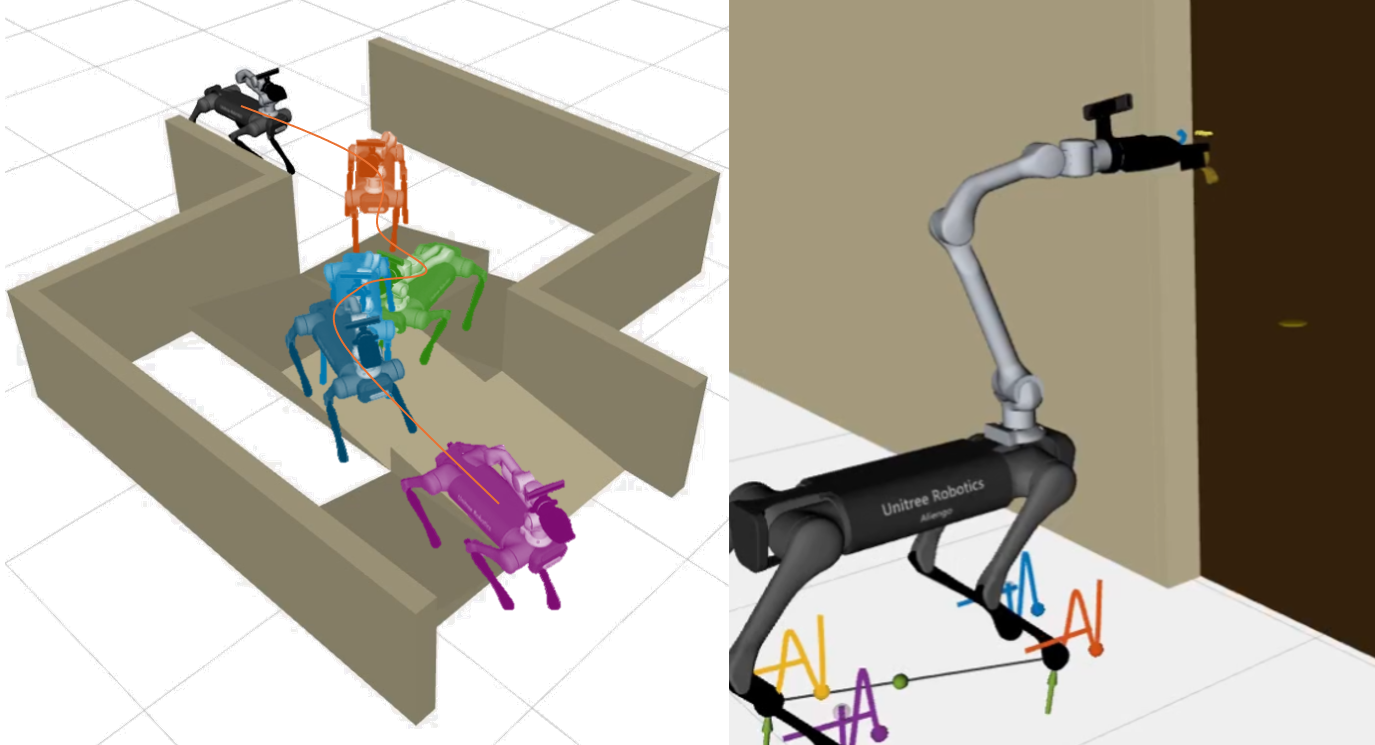
At the Technical University of Madrid, the RobCib research group has been actively developing advanced robotic systems for SAR operations. The primary focus of this project is the development, implementation, and testing of a Nonlinear Model Predictive Control (NMPC) system for the Unitree AlienGo quadruped robot equipped with a Z1 robotic arm. Through this advanced controller, the main objective is to enhance the robot’s capabilities for navigating unstable terrain and performing tasks such as door opening. The project integrates three modules involving computer vision, planning and NMPC control, and is built in ROS Noetic.
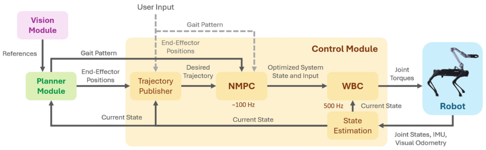
Based on OCS2 and ros-control, the developed NMPC-WBC controller facilitates tasks such as whole-body planning, end-effector motion tracking, and maintaining stability under force disturbances. The project builds upon the remarkable open-source contributions by SkyWoodz and QiayuanL.
NMPC Control Module Permalink
NMPC Control System Permalink
NMPC is an advanced control strategy designed to handle dynamic systems with nonlinear behavior. It predicts future system behavior and optimizes control actions in real-time. In this project, NMPC is used to control both locomotion and manipulation of the quadruped robot. The NMPC optimization problem is formulated as it follows:
In the problem, is the switching time, and is the final time. For each mode, the nonlinear cost function consists of a pre-jump cost, , that indicates the desirability of ending states before a switch occurs; and a cumulative cost over each interval, , that accounts for example for the error from a reference trajectory. The system flow map is driven by the system dynamics , and the system jump map, , defines how the state changes discontinuously at the time of switching , reflecting changes due to new foot contact state.
State and Input Definition Permalink
The robot has a total of 18 DoF, 12 corresponding to the quadruped and 6 of the Z1 arm. This way, the optimal control problem is formulated according with the system state and input defined as:
where is the collection of the normalized centroidal momentum, is the base pose and are the joint positions. are the contact wrenches acting on the end-effectors (note that it is assumed that the foot contacts are only subjected to 3-DoF forces and the manipulator end-effector is subjected to a 6-DoF wrench since it can also suffer a torque actuation) and are the joint velocities.
Cost Formulation Permalink
The NMPC cost formulation is simple and just defined by the quadratic cost of tracking the error of all states and the input:
where is the standard weight matrix, and is the control weight matrix; both positive definite matrices that act as important tuning parameters of the NMPC planner.
Constraints Permalink
With respect to the constraints, four types of state-input equality constraints and four types of inequality constraints are implemented. The state-input equality constraints are the following:
where is the linear velocity of contact point expressed in the inertial frame , and is the set of foot end-effectors. is the set of arm end-effectors, and and are the current and desired end-effector positions, respectively. is the force exerted on the end-effector and the force commands generated by the NMPC system. The equality constraints have the following implications: the foot of a stance leg should not separate or slip with respect to the ground, wrenches at open contacts vanish, all swing legs should track a reference trajectory along the surface normal, and the end-effector position tracks the desired one, as well as the externally applied force. The inequality constraints are the following:
where are the signed distances between pairs of links that are represented with primitive collision bodies, and is the minimum allowable distance between collision pairs. is the static friction coefficient and is needed to smoothen the friction constraints. The inequality constraints have the following implications: the joint positions must not overpass their physical limits, the same applies to the joint velocities, robot’s self-collisions are avoided with a certain margin , and finally, the forces acting on the feet lie in their respective friction cones, that is, the maximum static friction is not overpassed.
Optimization Problem Numerical Solving Permalink
To solve this optimal control problem, a direct multiple shooting method is formulated to transcribe the optimal control problem to a non linear program problem, which is solved using SQP. The QP subproblem is solved using HPIPM. The outputs of the NMPC planner are the optimized state and control input, and , which are passed to the WBC controller. The time horizon of the NMPC planner is s, and the loop computes feedforward trajectories at an average update rate of 100 Hz.
Whole-Body Controller (WBC) Permalink
The optimal reference plans for the base and limbs are tracked by a WBC controller that tries to fulfill a set of prioritized tasks. These tasks are formulated as a hierarchical QP that optimizes for the generalized accelerations and contact forces. The purpose of the WBC is not to directly track the optimal ground reaction forces but to capture their influence by tracking the reference motion they induce on the base to keep the robot balanced. This is because the WBC adjusts the optimized forces from the NMPC if they violate any high priority objectives. The only exception are the arm contact forces since the WBC has no knowledge of the manipulated object’s dynamics. WBC only considers the current moment, and each task corresponds to equality or inequality constraints dependent on decision variables. The decision variables for the WBC are:
where are the accelerations of the generalized coordinates. The computation of these decision variables is made through a series of calculations from and . The following table shows the WBC prioritized tasks list:
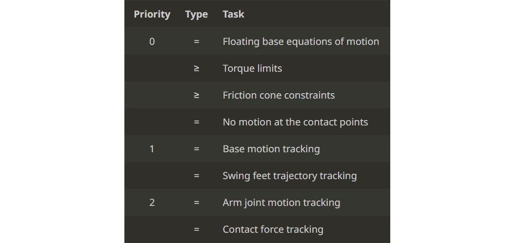
The WBC solves the QP problem in the null space of the higher priority tasks’ linear constraints and tries to minimize the slacking variables of inequality constraints. This approach can consider the full nonlinear rigid body dynamics and ensure strict hierarchy results with good real-time performance. The outputs from the WBC are the optimized joint position, velocity and torque references for the low-level control module: , , and , respectively. The actuator torque commands, , are generated by the low-level control module running at 2 kHz, according to the following equation:
where and are matrices with control tuning parameters corresponding to the proportional and differential gains of each of the 18 joints of the quadruped manipulator.
State Estimator Permalink
The state estimator consists of a Extended Kalman filter (EKF) which fuses the motor encoder readings, the visual odometry from the AlienGo front camera, and the IMU measurements to estimate the base pose and angular velocities, and the joint positions and velocities. This state estimation is fed into both the whole body planner and the controller. The WBC, along with the state estimator constitute the main control loop running at 500 Hz.
Vision Module Permalink
An advanced computer vision system allows the robot to autonomously interact with its environment. The system is designed to detect and manipulate door handles, enabling the robot to open push doors without human intervention. It uses information from two depth cameras to accurately position the robot and manipulate objects in controlled environments. Two YOLOv8 models were trained for door detection and handle classification and segmentation, and four ROS nodes were programmed to perform the different vision-related door opening tasks.
Planning Module Permalink
The planner module developed in this project is not a general-purpose navigation planner for obstacle avoidance, as this was beyond the scope of this project. Instead, the primary focus was on the control aspects of the robot, leveraging the existing NMPC controller for locomotion tasks, and developing a specific planner for door manipulation. In general locomotive tasks, such as the SAR environments where the robot will be tested, the trajectory publisher integrated within the NMPC controller assumes the role of the planner, generating references for the base from the end-effector commands. For door-opening tasks, a specialized planner was developed within the ROS package.
Simulation and Real-World Testing Permalink
Simulations were conducted using the Gazebo platform to evaluate the robot’s performance in various SAR scenarios such as navigating uneven terrain, climbing stairs, and opening doors. In addition to simulations, real-world tests were performed to validate the system’s performance. These tests provided insights into the robot’s capabilities in practical SAR scenarios.